PowerCharge
Products
PowerCharge

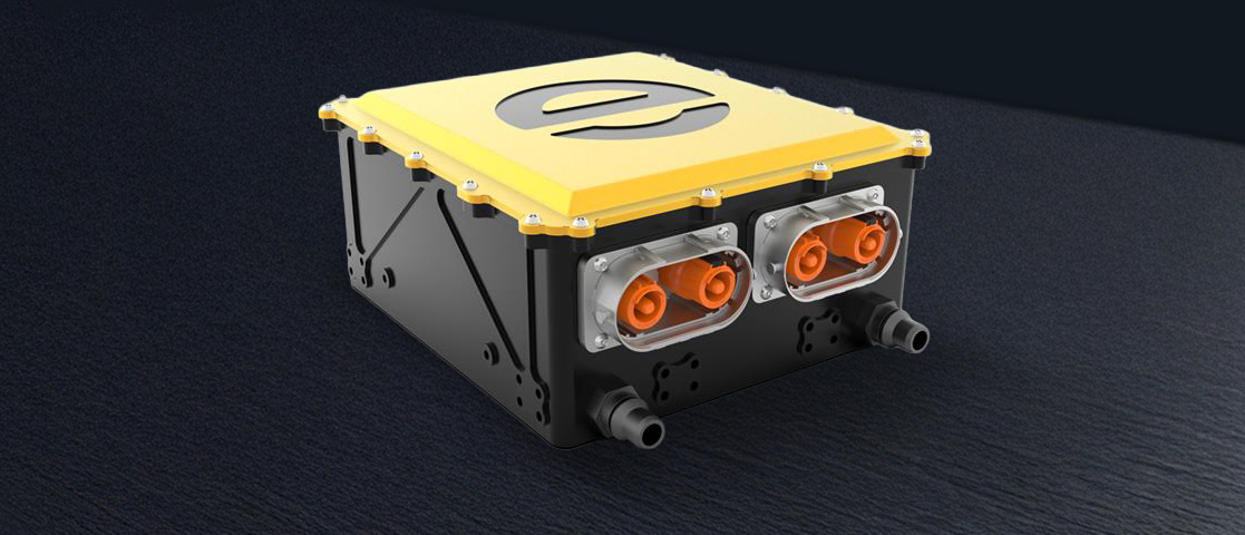
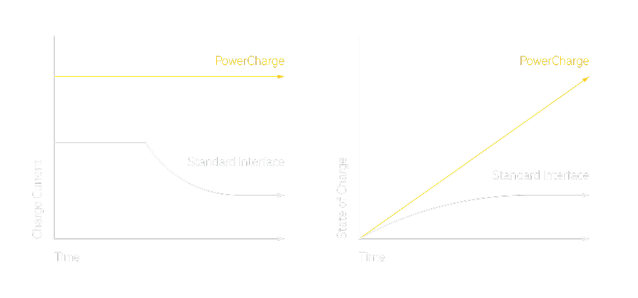
Reduce your charging time considerably with the PowerCharge. With a high peak current of 1000A and a long peak current time, the charging power can remain constant at up to 800 kW. The integrated electronics take care of thermal management, power reduction and contactor activation. Safe voltage measurement ensures the electrical safety of the vehicle’s charging connection.
01.
Powerful
Delivers up to 1000A peak current in a compact, water-cooled module.
02.
Safe and intelligent charging control
The built-in electronics take care of voltage measurement, activation of the contactors and thermal management – all via CAN.
03.
Ready for integration
Standard interfaces, optional inlet control and conformity with automotive standards simplify implementation in your system.
Tech Specs
Description
The PowerCharge receives high-voltage direct current from the inlet and forwards it to the vehicle’s high-voltage system. The PowerCharge contains the DC charging switches as well as the necessary safety measurements required for DC charging. Everything is controlled via CAN by the built-in electronics to maximize charging performance over the entire charging cycle.
Norms and Regulations
Charge current

Specification overview
Charge current

Connections
Pinning LV connector X1
| Pin | Pin name | Pin Description |
| 1 | GND | ECU ground |
| 2 | VCC | ECU supply, 6..32V |
| 3 | Wake up | ECU Wake-up, 6..32V |
| 4 | CAN_H | CAN High, 500 kBaud, no internal resistor |
| 5 | CAN_L | CAN Low, 500 kBaud, no internal resistor |
| 6 | Locking_in | Optional: Interlock circuit, 200mA max |
| 7 | Locking_off | Optional: Interlock circuit, 200mA max |
| 8 | GND_contactor | Optional: Contactor ground |
| 9 | VCC_contactor | Optional: contactor supply, 10..32V |
| 10 | n.c. | Not connected |
| 11 | n.c | Not connected |
HV connections
| Name | Description |
| X10 | DC charging input from inlet |
| X20 | DC charging output to the battery |
Product dimensions

